| FM-KF700 SERIES ELECTROMAGNETIC FLOW METER |
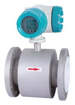
| FM-KF700 electromagnetic flow meter is an inductive apparatus to measure the flow volume of electric medium in the tube. The flow meter composes of sensor and converter, the flow meter design is adopted of SCM built-in technology to realize digital inciting magnetism the SCM connects CAN bus-mastering in the electromagnetic flow meter at the same to time. The electromagnetic flow meter can not only be read straightly but also output 4��20MA current signal for purpose of memory, adjustment and control. The flow meter is extensively used in industry technology and administration department such as chemical industry, environmental protection, metallurgy, medicine, paper making and water supply etc. |
 |
| FUNCTIONAL CHARACTERISTICS |
- The structure of flow meter is simple, function is reliable because there are no transmission parts, the working lifetime is long
- There are no block and cut-off parts, so the phenomenon of pres-sure loss and liquid block is not existed
- There is no mechanical inertia, fast response, excellent stability. It can be applied on automatic inspection adjustment and program process system.
- The preciseness of measure is free of physical data influence of medium varieties, temperature, viscidity, density and pressure etc
- The different configurations of both PTFE or rubber lining and electrical poles HC.HB, 316L, Tl etc can satisfy different medium requirements
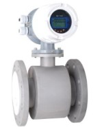
- There are two models: integration and separation
- High definition LCD displayer
|
| TECHNICAL DATA |
| Gauge preciseness: |
�� |
pipe style 0.5 grade,1.0grade;insert style 2.5 grade |
| Measure medium: |
�� |
all of liquids and liquid-solids whose electric conductance ratio is less than 5US/CM |
| Flow speed range: |
�� |
0.3~12m/s |
| Working pressure: |
�� |
0.6~4.0 MPa (According to the connection size) |
| Environmental temperature: |
�� |
-10��C~ +50��C |
| Medium temperature: |
�� |
PTFE lining�Q150��C rubber lining�Q65��C |
| Anit-explosion signal: |
�� |
Exd IIBT4 |
| Electromagnetic interference: |
�� |
<400A/m |
| Shell protection: |
�� |
integration style: IP65; separation style: sensor IP68, Converter IP65 |
| Output signal: |
�� |
4~20m, loading resistanceO~750Q |
| Transmission output: |
�� |
RS485 or CAN bus-line |
| Electrical connection: |
�� |
M20X1.5 female thread, 010 cord hole |
| Electrical power voltage: |
�� |
220��10%VACS 24VDC |
| Maximum power consumption: |
�� |
�Q10VA |
|
| APPARATUS SELECTION |
| In the normal industry application, it is better to set the measured medium speed as 2~4m/s, under the special situation, the minimum speed should be more than 0.2mIs and maximum speed less than 8mls, if there are solid granules in liquid, the usual speed should be less than 3m/s for purpose to avoid the over-attrition between lining and electrical poles, for viscid liquid, the speed can choose as 2m/s, the fast flow speed makes for the automatic elimination of obstructive substances glued on poles, therefore improve the inspection's preciseness. |
 |
DN |
Minimum flow volume selection |
Usual full range flow volume selection ( m3/h ) |
| 10 |
0.1 |
0.16, 0.2, 0.25, 0.3, 0.4,0.5,0.6,0.8,1.0,1.2,1.6,2.0,2.5 |
| 15 |
0.2 |
0.4,0.5,0.6,0.8,1.0,1.2,1.6,2.0,2.5,3.0,4.0,5.0,6.0 |
| 20 |
0.35 |
0.6,0.8,1.0,1.2,1.6,2.0,2.5,3.0,4.0,5.0,6.0,8.0,10.0,12.0 |
| 25 |
0.55 |
1.0,1.2,1.6,2.0,2.5,3.0,4.0,5.0,6.0,8.0,10.0,12.0,14.0,16.0 |
| 32 |
1 |
1.6,2.0,2.5,3.0,4.0,5.0,6.0,8.0,10.0,12.16,20,25 |
| 40 |
1.5 |
2.5, 3.0, 4.0, 5.0, 6.0, 8.0,10.0,12,16,20,25,30,40 |
| 50 |
2.5 |
4.0, 5.0, 6.0, 8.0, 10, 12,16,20,25,30,40,50,60,70 |
| 65 |
4 |
6.0,8.0,10,12,16,20,25,30,40,50,60,80,100,120 |
| 80 |
5.5 |
10,12,16,20,25,30,40,50,60,80,100,120,160 |
| 100 |
8.5 |
16,20,25,30,40,50,60,80,100,120,160,200,250 |
| 125 |
14 |
25,30,40,50,60,80,100,120,160,200,250,300,400 |
| 150 |
20 |
40,50,60,80,100,120,160,200,250,300,400,500,600 |
| 200 |
35 |
60,80,100,120,160,200,250,300,400,500,600,800,1000 |
| 250 |
55 |
100,120,160,200,250,300,400,500,600,800,1000,1200,1600 |
| 300 |
80 |
160,200,250,300,400,500,600,800,1000,1200,1600,2000,2500 |
| 350 |
105 |
200,250,300,400,500,600,800,1000,1200,1600,2000,2500,3000 |
| 400 |
135 |
250,300,400,500,600,800,1000,1200,1600,2000,2500,3000,4000 |
| 450 |
175 |
300,400,500,600,800,1000,1200,1600,2000,2500,3000,4000,5000 |
| 500 |
215 |
400,500,600,800,1000,1200,1600,2000,2500,3000,4000,5000,6000 |
| 600 |
305 |
600,800,1000,1200,1600,2000,2500,3000,4000,5000,6000,10000 |
| 700 |
415 |
800,1000,1200,1600,2000,2500,3000,4000,5000,6000,10000,12000 |
| 800 |
545 |
1000,1200,1600,2000,2500,3000,4000,5000,6000,10000,12000,16000 |
| 900 |
690 |
1200,1600,2000,2500,3000,4000,5000,6000,8000,10000,12000,16000 |
| 1000 |
850 |
1600,2000,2500,3000,4000,5000,6000,10000,12000,16000,20000 |
|
 |
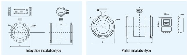
| MT-KF700 External Dimension For Integration And Partial Installation |
| DN (a) mm |
Working pressure (Bar) |
L |
D |
K |
n-��A |
Integration Weight (kg) |
Partial Installation Weight (kg) |
| 10 |
�� |
150 |
90 |
60 |
4-��14 |
6 |
4 |
| 15 |
�� |
150 |
95 |
65 |
4-��14 |
6 |
4 |
| 20 |
�� |
150 |
105 |
75 |
4-��14 |
6 |
4 |
25
32 |
40 |
150
150 |
115
140 |
85
100 |
4-��14
4-��18 |
7
9 |
5
7 |
| 40 |
�� |
150 |
150 |
110 |
4-��18 |
10 |
8 |
| 50 |
�� |
200 |
165 |
125 |
4-��18 |
12 |
10 |
| 65 |
�� |
200 |
185 |
145 |
8-��18 |
17 |
15 |
| 80 |
�� |
200 |
200 |
160 |
8-��18 |
17 |
15 |
| 100 |
�� |
250 |
220 |
180 |
8-��18 |
22 |
20 |
| 125 |
16 |
250 |
250 |
210 |
8-��18 |
24 |
22 |
| 150 |
�� |
300 |
285 |
240 |
8-��022 |
35 |
33 |
| 200 |
�� |
350 |
340 |
295 |
8-��22 |
45 |
43 |
| 250 |
�� |
400 |
395 |
350 |
12-��22 |
84 |
82 |
| 300 |
�� |
500 |
445 |
400 |
12-��22 |
102 |
100 |
| 350 |
�� |
500 |
505 |
460 |
16-��22 |
123 |
121 |
| 400 |
�� |
600 |
565 |
551 |
16-��26 |
147 |
145 |
| 450 |
10 |
600 |
615 |
565 |
20-��26 |
212 |
210 |
| 500 |
�� |
600 |
670 |
620 |
20-��26 |
229 |
207 |
| 600 |
�� |
600 |
780 |
725 |
20-��30 |
252 |
250 |
| 700 |
�� |
700 |
895 |
840 |
24-��30 |
352 |
350 |
| 800 |
�� |
800 |
1015 |
950 |
24-��33 |
462 |
460 |
| 900 |
�� |
900 |
1115 |
1050 |
28-��33 |
�� |
550 |
| 1000 |
6 |
1000 |
1235 |
1160 |
28-��36 |
�� |
680 |
|
 |
| Sensor Type |
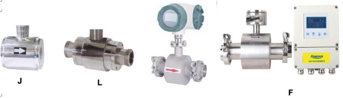 |
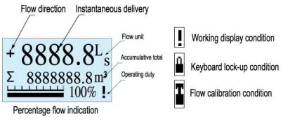
| Flow Display Interface |
 |
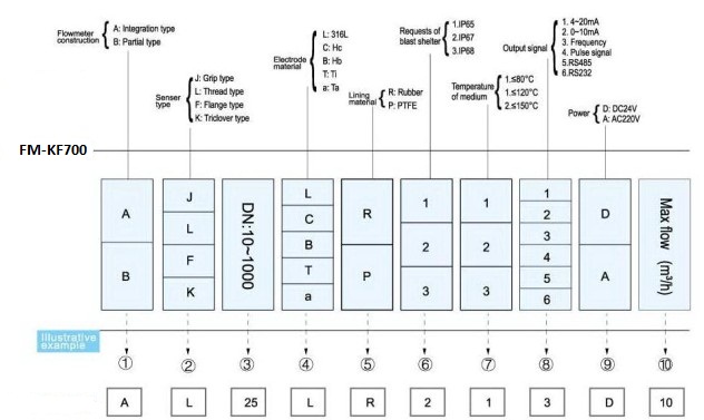
| Ordering |
 |
|
